
TBI 350 Installation
|
Tech information furnished by Brian Swearingen ECM Pinout Image 1 ECM Pinout Image 2 ECM Pinout Image 3 ECM Pinout Image 4 ECM Pinout Image 5 ECM Pinout Image 6 ECM Pinout Image 7 Complete 1990 Van P-series wire diagram Complete 1990 Van G-series wire diagram NOTE: original wiring found in most passenger fans is the G-series system....systematic cleanup of the wiring should simplify everything to what's found in the P-series diagram. BOTH are required to effectively clean up your stock wiring harness. When I installed my 1991 TBI-350 motor, I eliminated a few sensors but did keep most. KEEP: ELIMINATE: OPTIONAL (depending on application) Now, for the installed/finished photos.... Shot of the stainless custom dash insert....opted to run no speedo or odometer, but instead run a tach, oil, water, volt, and hourmeter in there. There is also a red LED for the Service Engine light just below/right of the Oil pressure gauge. 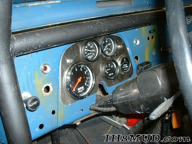 Drivers side photo showing the hugger headers, the O2 sensor location off the backside of the header above the collector, and the clearance with the Flaming River steering joints and DD shaft. 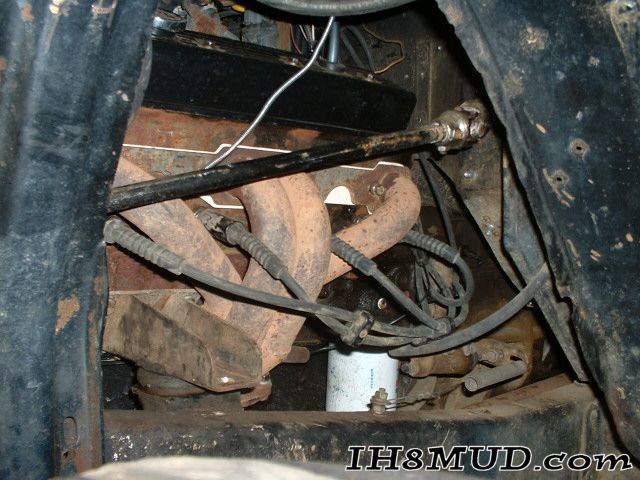 Drivers front corner shot, you can see the steering column pillow block in the background, the Ford shock towers, and the custom bump stop for the pitman arm so the springs don't contact. 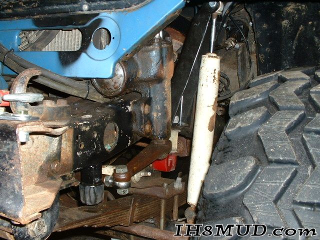 Passenger front, again showing the shock tower and you can see the relocated Knock sensor. This was moved from it's factory location to the fuel pump block off plate, and a pipe-thread cap was welded on to thread it in. 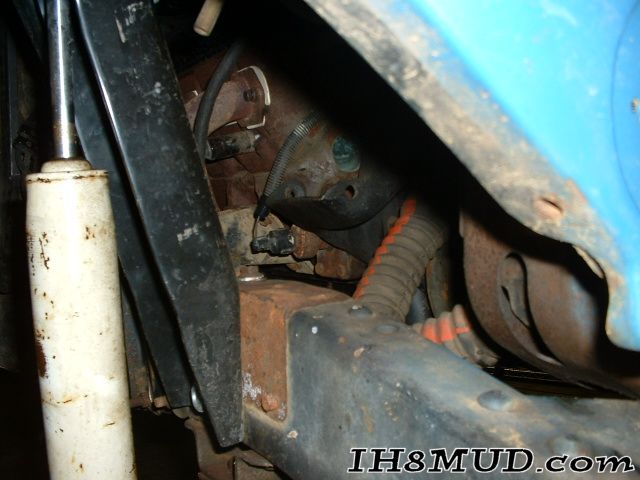 Passenger side, you can see the starter with the factory shield in place, the Knock sensor, and some of the loomed wiring. The knock senser factory location was behind where the header is located now. It was in a water jacket, so that hole was plugged. 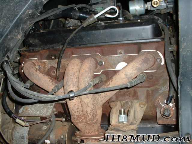 Passenger side again, upwards towards the intake, showing my temporary hookups for the AC compressor (Harrison-style, see how long it lasts). 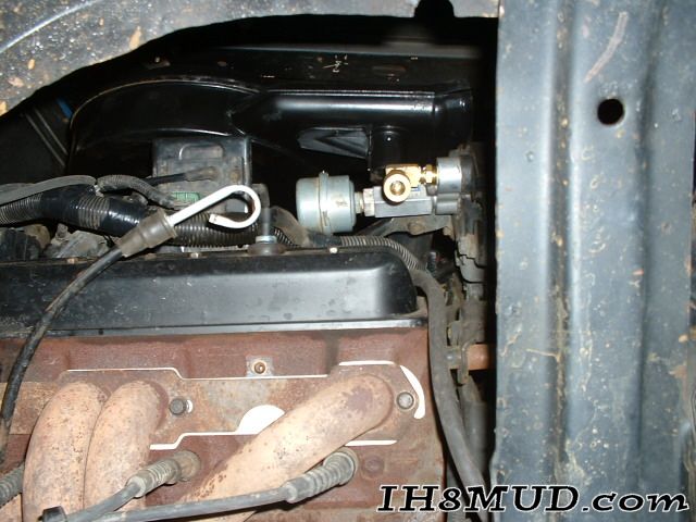 Drivers side, good shot of the routing of the stock 1991 chevy van speedo cable 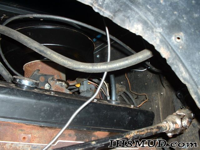 Drivers side hood open this time....PS remote reservoir, fan/clutch (no shroud yet), alternator, and the PS fluid cooler location. 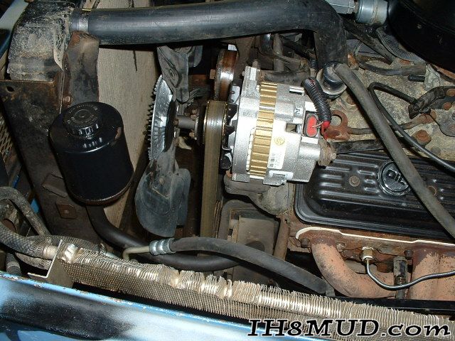 Front view of the drivers side, can see the oil and temp line routing, and most other stuff. 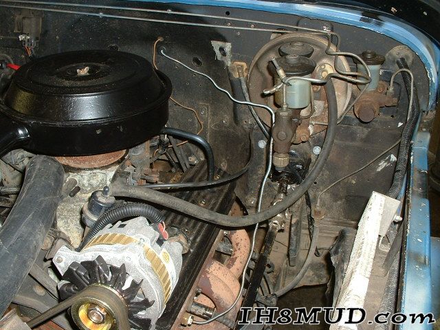 Passenger side front shot. 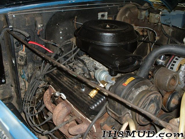 Firewall shot showing where the grommet for the wiring goes thru and the location of the fuel pump relay on the firewall. 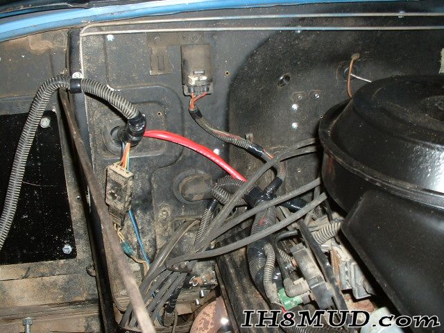 Computer and ALDL shot, located beneath the glove box. The green coiled wire is the input for when the AC is turned on, may use that as a cheater for increasing idle while winching. 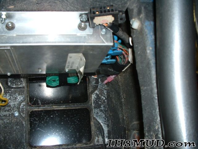 Spaghetti...not yet cleaned up, but this is where the wires from the computer link into the hot and switched fuse blocks and where the wires from the TBI harness meet up with the factory one. 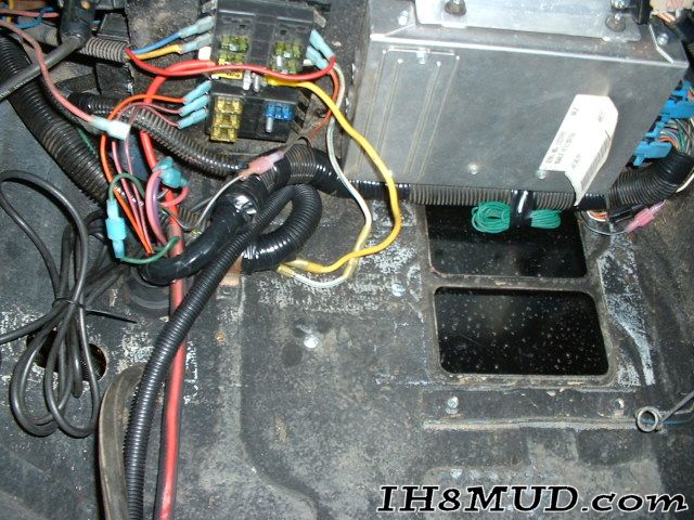 ...more spaghetti....not as bad as it looks really...seriously... 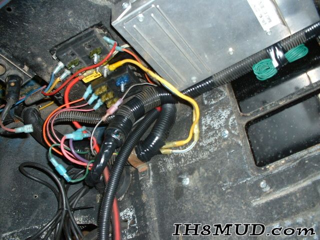 Underdash shot...shows where the oil and temp come thru the firewall and some of the underdash loom work. 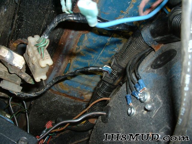 Drivers seat shot....batteries under the seat and the isolator. Still need to do some wire work or swap isolators since the CS130 Alternator likes a different wire setup than the old one. 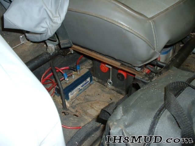 One more from under the passenger seat....all will have black loom when done to protect it from my clumsy feet... 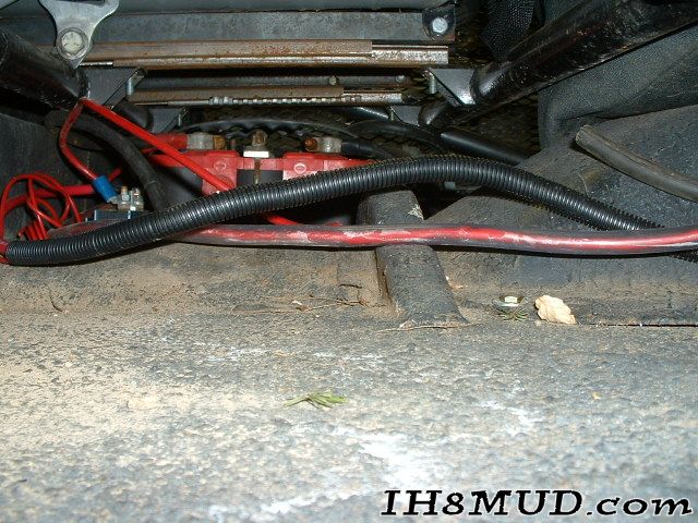 Drivers seat, showing seat brackets and adjustment, dual batteries, and my 1000amp ground-side disconnect. 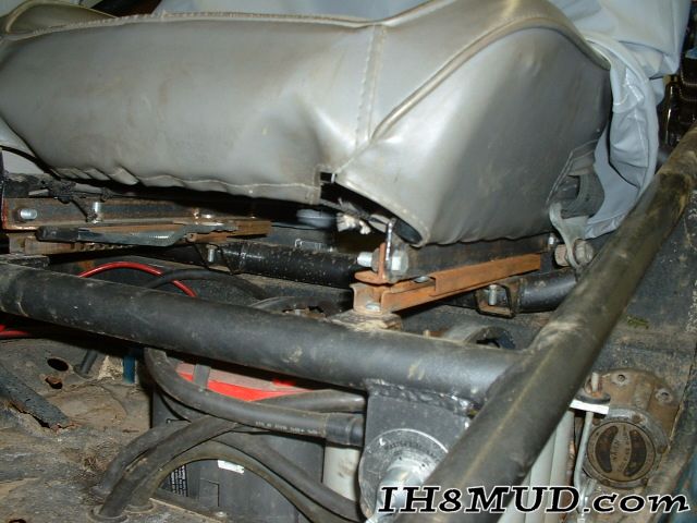 High-lift jack location; 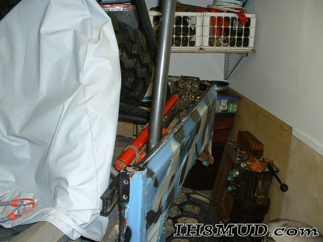 Fuel cell, hi-lift, spare tire clamp. 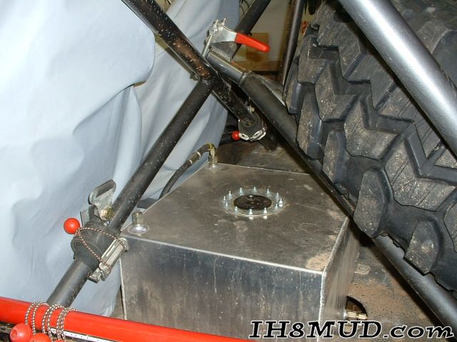 And finally the open hood shot....all complete and no codes! :grin:  Posted March 26, 2003 |