
FJ40 - Scout Saginaw power steering conversion.....
Originally performed May 1996, 2nd project Winter '97-'98
Alco check out some of Morgan Fletcher's FJ55 install photos at http://www.off-road.com/~morgan/tech/scoutps/20000216/. |
I have performed this installation twice, once on my '74 FJ40, and again on my "new" '69 FJ40. My first install left a bit to be desired, so hopefully this will cover all the mistakes I made.
As you are shopping for parts, remember that different installations will require slightly different parts lists. V8 FJ40's will be able to use most any PS pump, providing the line connections are workable. You will also want the bracketry from the block for installation. Toyota I6 installers will want the pump/brackets off a Chevy inline 6. These are modifiable relatively easily to the existing Toyota block. For additional details on the inline 6 install, see Jim VandeVen's page above.
TOOLS/EQUIPMENT REQUIRED:
PARTS/COSTS:
DON'T FORGET THE BOLTS/BRACKETS!!
PREPARATION:
- Clean, clean, clean....you will have a significantly easier install if your workspace is clean....nothing worse than getting last years mud in your eyes! Clean the frame inside, around the shock tower, the firewall, and all the parts you've brought home.
- Remove the drivers side fender and the front bib. Un-bolt and slide the radiator over so it's out of the way. If you have the fenderwell-exit V8 headers, you'll need to un-bolt these as well and lift up out of the way. Un-bolt the shock and remove. Remove the stock center arm and steering box. (Removing the box mounting bracket is optional) Disconnect your battery.
- Torch off the engine-side rib of the shock tower entirely. Grind flat. Also grind a notch in the outer forward-portion of the shock tower where it's riveted to the frame. Grind flush with the existing frame and back to the edge of the rivit. This is done so the box is positioned far enough back to only require minimal trimming of the front bib.
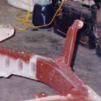
- Cut/make a 3/16" thick plate for inner frame reinforcement. This should extend from the center of the shock tower forward (@ 8" or so). Weld into place. (see photo at right)
- Position the steering box on the frame and clamp into place. Align the single bolt hole in the notch you made on outer shock tower. Check all points for sufficient clearance, parcitularly where the rag joint will go. You may need to grind a portion of the rearward shock tower rib for clearance. Recheck all positioning....once you drill, you're committed.
- Once you're happy with the positioning, drill a single hole thru the frame at the rearward bolting tab (closest to the shock tower). This will be the pivot point you use to align the rest of the linkages. DO NOT drill/mark the forward two holes yet! Clamp the box tightly in place, with the rearward bolt in place as a pivot.
- (I used a '77 steering column on both installations, so yours may differ slightly at this point.) Cut the rag joint flange off the end of the steering shaft and grind smooth. Assemble the u-joint and slip-fit into place. Cut off one end of the "new" steering shaft and grind smooth...remember you need the rag-joint end for attachment to the "new" steering box! Drill out any nylon pins in the shaft and convince it to adjust. Slip fit the ground end of this shaft into the u-joint and adjust length such that the rag joint is not twisted. You may need to adjust both shaft length and box angle. Once completely happy with all the alignments, tighten the set screws and weld. (I welded mine in place, with an assistant turning the steering wheel. You can also remove the steering column for this, just make sure nothing shifts.) Reinstall in the truck and double check the fit.
- Recheck your rag joint for position and if satisfied, drill the two remaining holes for securing the steering box. NOTE: I originally did not sleeve my holes and began to have problems. I bought a pipe where the ID allows your bolt to fit. Drill the exterior hole equal to the OD of the pipe, then using the bolt to align everything, weld into place.
- Check your steering shaft length and check the rag joint. Once set, drill thru shaft and install a new nylon crush pin. (You can likely reuse the outer holes)
- Position the "new" tie rod by loosely attaching it to the steering arm. Mark for cutting about 8" from the hole on the Toyota tie rod. Cut the Scout rod. Then position your Toyota rod and cut for maximum overlap (just short of the bend in the Scout rod). Slip the Toyota rod inside the Scout rod, check your steering wheel for center, then weld solidly.
- Installing hoses and the pump will vary by installation...since mine was a GM pump on a GM motor, it was quite easy...make sure you get every support bracket available for the pump...I originally only had it mounted at two places, and it would twist and eat up belts. I discovered I was missing a 3rd mounting point and adding that bracket made a huge difference. I have not found the need to run an oil cooler off the return line.
- Steering with the stock pitman arm can be a bit quick...I swetched recently (1/00) to a shorted arm off a Camaro. The change shortened my swing by about 1.5" and eliminated the stock drop found in the Scout arm. I needed to re-ream the holes to fit the Scout rod end.
- IMPORTANT! When you cut the Scout tie rod for your new drag link, take note of which rid end you will end up using. Scouts used a RH thread on both ends, one coarse and one fine....make sure you use the fine one!! The coarse one is very difficult to locate in the parts houses. (I finally gave up and am switching to a custom rod-end setup!)