
Cruiser Carb Info
|
Tech information furnished by Ed Cook Tinkering a 73 or 74 USA TLC carb will provide performance equal to non-USA TLC and webber progressive carbs. Earlier USA TLC carbs were jetted to run on air alone. The aim here is to improve low rpm and part throttle driveability.THEORY Carbs have 6 circuits that maintain stoichiometric gas/air mixture for all combinations of rpm, throttle position and changing throttle positions. Circuits are main, off idle, idle, power valve, accelerator pump, [?] choke, and float-bowl. See fig. I 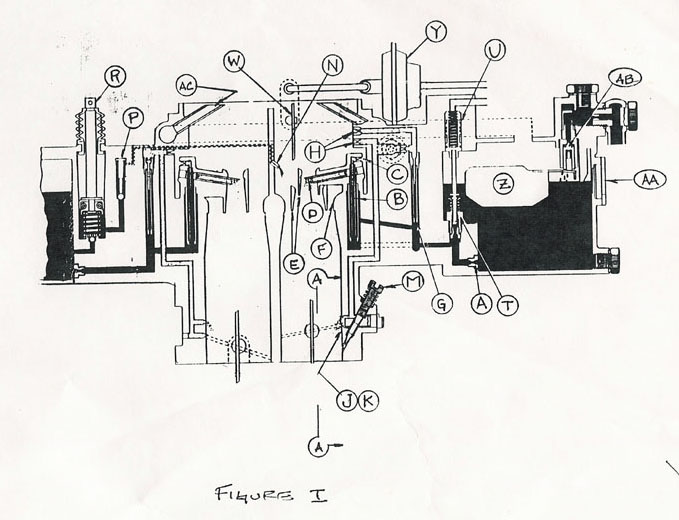 Main circuit consists of mainjet (A), emulsion tube (B) air correction jets (C) nozzle (D) booster nozzles (E) and venture (F). Venture provides reduced static pressure at neckdown point which can be used to pull gas up from float bowl and into engine. Reduction of static pressure (delta P) increases with increasing air flow thru venture. Booster nozzles are additional mini venturis which boost delta P signal. Nozzle is a tube positioned midway between main venture and inner booster venture. This is where main circuit gas flow is pulled into engine Air correction jet is positioned upstream of nozzle. Static pressure at theis point is till less than atmospheric static pressure and air enters here to froth gas/air mix, like the head on a beer. In this state each gas molecule is right next to an oxygen molecule and combustion efficiency is improved over crops of gasoline. Emulsion tube is positioned upstream of correction jet. Emulsion tube works in conjunction with air correction jets to emulsify the mix. Brass portion of emulsion tube also has "air correction jets", which are submerged during engine off condition. Lower jets are uncovered with increasing air flow thru venture. Design parameters here involve black magic. Main jet is positioned upstream of emulsion tube and at bottom of float bowl. Jet is a restriction which limits gas flow at high rpm and wide open throttle (WOT) conditions. Main jet feed idle and off idle circuits also. Idle and off idle circuits consist of main jet (A), idle jet (G), idle circuit air correction jets (H), throttle plate / bore interface (J), slot in bore (K), and idle mixture screw (M). see fig. II 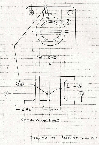 Idle jet and idle circuit air correction jets provide some function as main circuit emulsion tube and air correction jets. Idle jet also limits maximum gas flow thru idle circuit. Throttle bore and partially open throttle plate form crescent moon shaped interface / neckdown which forms crude venture with associated delta P signal. Slot in throttle bore is exposed to delta P signal as throttle is opened up to ~20 deg. For throttle angles of 20-5 deg (idle) as all rpms there is insufficient delta P signal at main circuit nozzle to pull fuel into engine. Idle to main circuit transition point may be easily observed by looking at the main circuit nozzle while slowly opening throttle. Idle mixture adjustment (adj) screw and associated hole in bore provide tapered needle and seat valve, used to fine tune hot-idle gas/air mix. Accelerator pump circuit consists of spray nozzle (N), check valve (P), and plunger & check valve (R). Nozzle sprays a stream of gas into entering air stream when throttle is opened quickly. This short lived spritz quickly and temporarily corrects for potentially lean condition. Plunger plunges to squeegee gas towards nozzle. Both check valves prevent gas flow thru this circuit during static throttle conditions. Note nozzle location with respect to venturis. Downstream check valve is weighted closed more strongly to allow gas to be squeegeed back into float bowl with exceedingly slow throttle opening rate. Power valve circuit consists of normally sprung closed check valve (T) and normally delta P closed (lack of vacuum spring opened) piston (U). this circuit takes over enrichment function after accelerator pump circuit has spritzed. When throttle is jammed open, intake manifold vacuum drops from ~18 inches Hg (9 PSI delta (?)) to near zero. Preloaded spring behind piston opens power check valve, effectively adding extra main jet, enriching [?] main circuit. When speed, rpm, and delta P build to near steady state conditions of delta P are greater than or equal to 10 inches Hg, delta P signal will overcome spring force and close power valve. Power valve circuit operation may be observed/sensed by removing an accelerator pump circuit link and driving [it] around. When throttle is opened suddenly engine should bog down then pickup, within ~.7 second. Choke circuit consists of choke plate and shaft (W) fast idle linkage (X, not shown), choke pull off (Y) and choke cable (not shown). This circuit enriches mixtures for all operations conditions, depending on how far choke knob is pulled out. When choke knob is pulled out fully, choke plate closes and throttle plate is opened ~10 deg. Oversimplifying things a bit; rotating / starting engine cannot pull in much air, so it pulls in gas from every pore downstream of choke plate. The choke plate is actually sprung closed and pivoted off-center to allow increasing air flow to force choke plate open and to permit choke pull off to open choke plate ~20 deg, avoiding over rich mixture at fast idle. Cold start conditions cause emulsified gas to condense on intake manifold walls and enter combustion chamber in droplet form, reducing engine efficiency, necessitating enriched mixture and increased idle speed. Float bowl circuit consists of float (Z), float bowl (AA), and fuel inlet needle & seat valve (AB). Float and needle & seat valve work together to control float bowl fuel level. Float level dictates delta P signal level required to pull gas up and into engine. Performance at severe off level conditions has been considered in OEM TLC carb design. Carbs in General (progressive 2 brl carb opens primary throttle plate only, for gas pedal positions of less than or equal to 33% full open.) Holley, Rochester, and Webber carbs are offered as aftermarket "upgrades". Webber progressive carb is better than OEM TLC carbs. Carbs with simultaneous throttle plate action are also available (holley, Rochester, webber). The simultaneous style carbs have venture diameters of 35-40 mm, whereas OEM TLC carb has venture diameters of 28 & 31 mm; webber progressive has 32 &36. the simultaneous style carbs have larger venturis and higher flow ratings ('cfm') and will provide lower 0-60 mph times and better performance at extreme high rpm (~3500). At low rpm with gas pedal opened 33%, delta P signal is at it's weakest level (white lie). Simultaneous style carb cuts delta P signal in half, and secondary reduction of delta P signal occurs due to larger combined venture diameter. White lie goes away for progressive carbs with vacuum actuated secondary throttle. Webber progressive carb (32/36) is fitted to Toyota 4cyl truck engine (2000cc) so it's not oversized for TLC engine (3700/4320 cc). webber has 2 brl progressive with vacuum actuated secondary, but I have not sent it offered for TLC. Routine external replacement of main, idle, air correction jets, and emulsion tubes is possible on webber carbs. Webber have their own unique ideas for manual choke circuits, so it's best to stick with automatic choke. Fuel injection provides the best system with the best of all worlds, and only those compromises you dictate. Sequentially multiport preferred, throttlebody ok. USA OEM TLC carb Upgrades Starting point should be one or more 73-74 USA OEM TLC carbs. 73-74 carbs incorporate several low speed/rpm driveability improvements over 70-72 issues. 75-78 OEM issue incorporates vacuum actuated secondary throttle but require Ph.D. in physics to maintain and operate. Disassemble, make notes, clean, and check and correct flatness of mating surfaces. Then put it back together with the right pieces. Beware of previous efforts to attain five sec 0-60 times by mixing up jets and venturis. Use MoS2[sp](?) grease, graphite lubricant is a no-no for steel to aluminum/zinc threaded interfaces. Primary and secondary (P&S) venturis should be 28&31 mm respectively. P&S main jets should be 1.20 & 1.80 mm respectively. Older issue had 1.42/2.00. richens primary circuit and leans secondary circuit. P&S idle jets should be .50 and .80 mm. older issues has .50/.50. richens secondary idle circuit. Primary idle circuit jet diameter increase might benefit low rpm performance. Emulsion tube / nozzle assembly is not so straightforward. 73/74 issue eliminates a ring of air correction jets at upper portion of brass emulsion tube. This improves main circuit performance at low rpm. Also lower ring of air correction jets have reduced hole size. This leans mixture at high rpm. Second improvement is addition of second booster venture to secondary throttle bore to smooth transition to two throttle plates open. Power valve jet is .80 mm for 73/74 issue and .90 mm for older issue. Leans mixture, but ok given previous changes. Spring free length should be 1.75 inches. Spring will take a compression set in 20 years, if it is overstretched. Accelerator pump circuit is unimproved. Spritzer nozzle is prone to clogging at diameter of .023". spring on vertical link should be statically precompressed 0-.5". two fast idle linkage positions are available. For cold climates select faster fast idle. Choke circuit is TLC weak point. If it ain't broke Problem is failure of choke plate to close. Reasons are torsional spring major diameter shrinks when exercised and thrust load due to torsional springs causes entire side of choke plate to scrape against wall. Solution: fit thin (.010") brass thrust washer to rear choke plate shaft housing interface. Also local shaft major diameter should be turned down to allow for collar/bushing between torsional spring, major diameter and local shaft o.d. 1975-87 2F owners are requested to comment of manual choke operation. (components might be switched over.) 1970-74 USA OEM TLC carb does not have "ported vacuum" port for vacuum advance distributor. Cast iron throttle plate housing has boss ready made for ported vacuum port (AD). Entrust machine work with good machine shop, or be willing to waste a few housings. Find brass tube ~.156" x .75" to press into depth of ~.25" (hobby shop or old carb). See figure II. Center punch a mark near center of boss and .96" above bottom surface of cast iron throttle plate housing. Drill thru with .020-.032" drill, radial to bore cross-section and perpendicular to throttle bore axis. With drill wander, lowest (optimal) hole centerline entry position is ~.90". assuming you've hit oil, drill hole for press fit of ~.156" brass tube into cast iron. This port should read 0 inches Hg vacuum at hot idle. -1970-87 USA OEM TLC carb does not have hand throttle provisions. 1 or 2 carbs must be sacrificed and a mig welder is nice. Scare up cable end clamp, crank arm, and cable housing clamp. True-up foot operated throttle cable housing bracket. With trial fitment, weld cable housing clamp to vertical portion of throttle cable housing bracket and weld crank arm to bell crank (beware of exhaust manifold interface and accelerator pump linkage interference whilst maintaining crank arm length of greater than or equal to 1.7") crank arm should have rotating and sliding eyelet. Normal throttle operation should not be compromised. (ref 1989 F.I. setup) engine braking effect can be increased by installing vacuum actuated electrical switch. Beneficial side effects are reduced emissions and reduced backfiring with suddenly closed throttle. A solenoid with shutoff valve permits gas to enter idle circuit during ignition on key position. To prevent "run on" solenoid closes idle circuit with loss of +12 volt signal (i.e. key off). This solenoid/shut off valve can be used to stop idle circuit gas flow when descending steep hills. Grounding solenoid thru vacuum switch (which opens ground circuit for intake manifold vacuum in excess of ~23 inches Hg) is the trick. 1976-87 carbureted Toyota corolla or land cruiser have switch. Solenoid has ground wire. Use soldering gun/iron. Frame provides good ground (0 volts), fender doesn't. Keep positive crank case ventilation valve (PCV) in place. PCV keeps oil cleaner. Initial start-up & adjustment Triple check all work (including all of ignition system). Fit vacuum gauge and tach, fill float bowl with clean gas up to center of float bowl window using airhorn (AC). Set idle mixture screw two turns open, CCW from closed position. Set idle speed screw two turns open, CW from full closed position. Set fast idle adj screw so that linkage points just contact at hot idle setting. At 35 deg F pull out choke and fire engine up. Adjust fast idle to lowest stable rmp (+100 rpm)(+300 for cold climate). Monitor engine and push in choke until coolant temp reaches 150 deg F. adjust idle speed to lowest stable rpm (+25 rpm). Adj idle mixture screw as follows; starting at 4 turns out (overrich), screw in until rpm and vacuum drop off ("lean drop off point" / not crisp on OEM TLC carb) then turn screw just back to max vacuum reading (+1/4 turns). Utilizing vacuum gauge, advance ignition timing until vacuum peaks then retard timing such that vacuum reading is 1 inch Hg below peak reading. Use high test or aviation grade fuel. Repeat idle speed, idle mixture, and idle ignition timing adjustments 5 times optimizing adjustments at each stage. Retard ignition timing to avoid pre-ignition / pinging. For optimal emissions try 2 deg BTDC, 900 rpm & 50 rpm lean drop off. For futher reading; webber carb theory, tuning and maintenance, (2 books), John Passini, 1973, speedsport motor books, England. IBSN 0 85113 0607 & 0903192 40 3 . **idle mixture screw CW = lean CCW = rich idle speed CW = higher CCW = lower distributor CW = retard CCW = advance |